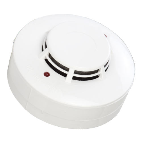
Ravel Conventional Smoke Detector Connection Diagram

Re317 Series Installation Wiring Diagram Manualzz
Http Ravelfire Com Wp Content Uploads 2015 06 Re316 Installation Manual Pdf
Re 316s 2l Welcome To Ravel Fire
Connecting 2 Wire Smoke Detectors
Yongningan Sfl 220v Gsm Photoelectric Smoke Detector With Relay Output Buy Yongningan Sfl 220v Gsm Photoelectric Smoke Detector With Relay Output Sfl 220v Gsm Photoelectric Smoke Detector With Relay Output Smoke Detector Alarm

Dk 9492 Fire Alarm Systems Fire Alarm System Diagram Free Diagram
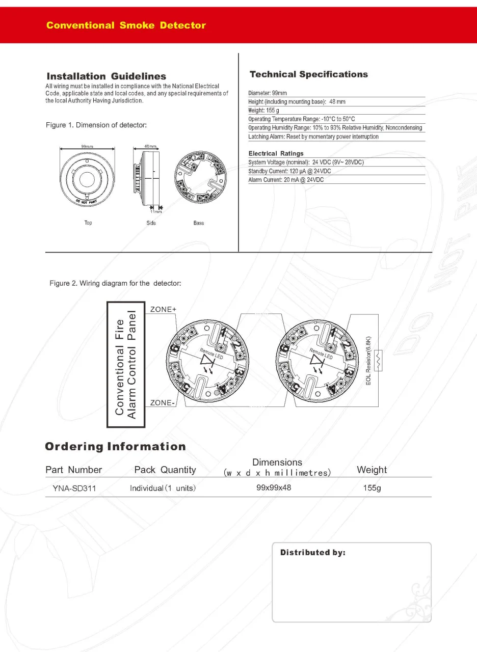
There are two types of fire panels conventional types which have zones which are connected directly to devices such as optical beam smoke detectors or flame detectors and analogue addressable types which have a loop bus onto which addressable devices can be connected.
Ravel conventional smoke detector connection diagram.

Fire Alarm Wiring Diagram Fire Alarm Smoke Alarms Alarm

10 Fire Alarm Installation Wiring Diagram Cable For Smoke Alarms Fire Alarm System Alarm Systems For Home Fire Alarm

Wiring Diagram For Fire Alarm System Diagram Fire Alarm Circuit Fire Alarm System Fire Alarm Alarm Systems For Home
Smoke Detectors Totaline Smoke Detectors Latest Price Manufacturers Suppliers

How To Install A Hardwired Smoke Alarm New Branch Circuit Smoke Alarms Hardwired Smoke Detectors

How To Install A Hardwired Smoke Alarm Ac Power And Alarm Wiring Smoke Alarms Hardwired Smoke Detectors

Conventional Fire Alarm System Fire Extinguisher Dealer Coimbatore Coimbatore

Welcome Fire Alarm System Fire Alarm Fire Protection System
Msr 320 Conventional Detector Base With Relay Fire Alarm System India

Avani Data Sheet Ravel Fire Ravel Electronics Fire Alarm Panels Manualzz

Fire Alarm Penal Connection Addressable And Setting On Simplex 4010 Tamil Youtube
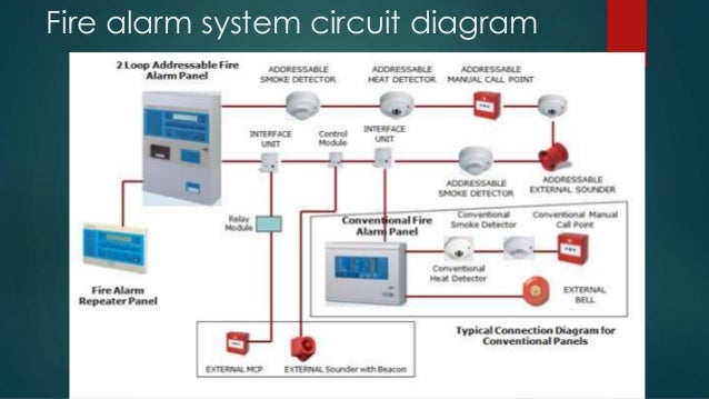
Diagram Simplex Fire Alarm System Owner Manuals Wiring Diagram Full Version Hd Quality Wiring Diagram Handsfreecash K Danse Fr
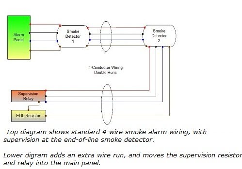
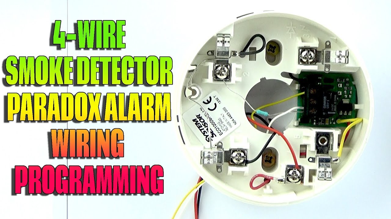
Connecting 4 Wire Smoke Detectors

Conventional 16 Zones Fire Alarm Control Panel Fire Alarm System Fire Sprinkler System Fire Protection System

Addressable Smoke Detector 2 Wire Aw Asd2188 View Addressable Smoke Detector 2 Wire Asenware Product Details From Sh Fire Alarm Smoke Detector Heat Detectors

Db 01 Gst Conventional Base Diamondelecticals
2 Wire Smoke Detector Wiring Paradox Evo Alarm Panel Youtube

Re 428 Series Beam Detector Termination Youtube
3

White Ravel Re 326 Sl Listed Optical Smoke Detector With Base Rs 550 Number Id 20980588662

Agni Fire Alarm Panel Working And Installation By Green Tech Solutions Agni Smoke Detector Youtube
Http Ravelfire Co Uk Downloads Im Re120gr Pdf

Gst Smoke Detector Gst Addressable Smoke Detector Wholesale Trader From Mumbai

Zone Interface Module Data Sheet
Source : pinterest.com
