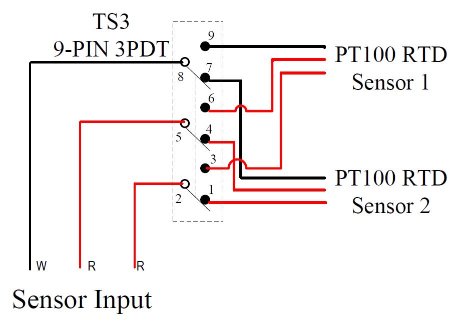
Rtd Temp Probe Wiring
2 3 And 4 Wire Rtds What Is The Difference
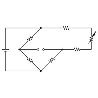
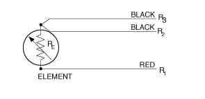
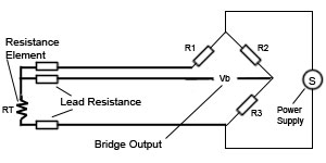
Rtd Wiring Diagrams

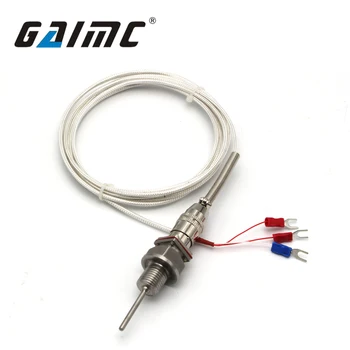
Visit To Buy 1m High Temperature Cable Pt100 K Type Thermocouple Rtd With 6mm Thread Thermometer 45 To 500 Degree Sensor Probe Ng4s Sensor Thermometer Probe
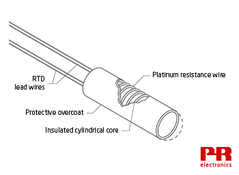
Rtd Temperature Sensors The Fundamentals

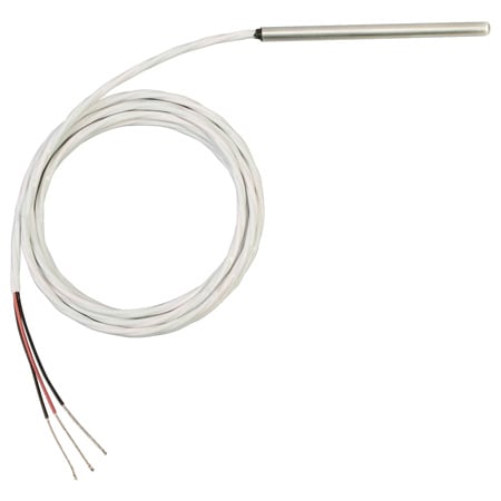
4 Wire Rtd Temperature Sensor Rtd Resistance Temperature Detector Rtd

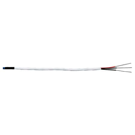
Rtd Wire 3 Wire Design 24 Gage Stranded With Fep Insulation 100 Ft Evolution Sensors And Controls

Rtd sensor in 2 wire circuit.
Rtd temp probe wiring.
Rtd Sensors 2 3 4 Wire Rtd Sensors Resistance Temperature Detectors

Resistance Temperature Detectors Leadwire Rtd Probes

Exposed Rtd Element Sensor Design With 48 Inch Long Leads And Connector Evolution Sensors And Controls

Rtd Wiring Config Adafruit Max31865 Rtd Pt100 Or Pt1000 Amplifier Adafruit Learning System

What Is An Rtd Rtd Types Uses And More By Jms Southeast
Connecting 2 3 And 4 Wire Rtds To My Data Acquisition Card National Instruments

Overview Adafruit Max31865 Rtd Pt100 Or Pt1000 Amplifier Adafruit Learning System

Crocsee Rtd Pt100 Temperature Sensor Probe 3 Wires 2m Cable Thermocouple 58 572 F 50 300 C 1 2 Npt Thread Amazon Com Industrial Scientific
Temperature Sensors Auber Instruments Inc Temperature Control Solutions For Home And Industry

How To Wire Your Rtd Get Proper Rtd Readings Youtube

Thermocouple Rtd Thermistor And Hook Up Wire

Emerson Rosemount 644 Temperature Transmitter Iecex With Pt100 Rtd Sensor Probe For Sale Online Ebay
2 Wire Rtd Support For Ni 9216 Ni 9217 Ni 9226 And Ni 9219 National Instruments

Pt100 Temperature Sensor Rfcse3 Rfcse5 Series Sterling Sensors Rtd Stainless Steel Flexible
Gts300 Three Wire Rtd Temperature Sensor Pt100 Pt1000 Buy Pt100 Temperature Sensor Pt100 Pt100 Sensor Product On Alibaba Com

Rtd Sensors Rtd Manufacturer Resistance Temperature Detectors
Pr 20 Series Short Rtd Probe Omega Engineering
Amazon Com Treager Digital Rtd Temperature Probe Garden Outdoor
1

Rtd Pt100 Temperature Sensor Probe 0 23 X 2 1 2 Npt Thread With 2 Meter Cable 50 To 300 Amazon Com Industrial Scientific

Surface Mount Rtd Temperature Sensor Evolution Sensors And Controls

Tempco Bare Wire Rtd Temperature Probe 0 To 900 Temp Range F 3fwx4 Rtd00577 Grainger
Rtd 2 F3105 Rtd Elements With Wire Lead Welded To Rtd Element Sensor Probe

Resistance Measurement 2 3 Or 4 Wire Connection How Does It Work And Which To Use
Source : pinterest.com
